Compressed Air Piping Design Handbook
The building codes and standards impacting the design and installation of compressed air systems have. Engineering Design Handbook. Erode piping and valves.
- D COMPRESSED AIR SYSTEMS APPLICATION AND SYSTEM DESIGN COMPRESSED AIR SYSTEM DESIGN A compressed air system made of thermoplastic piping is a simplified installation.
- ENGINEERING STANDARD. PROCESS DESIGN OF. And CAGI 'Compressed Air and Gas Handbook. The lowest air pressure in the inlet piping to the compressor.
Lower pressure drop by installing the right compressed air pipe size. Calculate the correct pipe size for your compressed air system. So, you want to know the correct pipe size for your compressed air installation? It easy, I’ll explain how.I still see too many places where the pipe size of the compressed air system is too small. It’s either because the factory or workshop has grown over time, and the old system became too small (quite understandable), or they just installed a too small pipe to begin with!What’s the problem with a too small compressed air pipe?
Pressure drop! If too much air needs to pass a too small pipe, it will have trouble passing through this pipe. The result is a pressure drop between the beginning of the pipe and the end of the pipe.

Now, what’s the problem with pressure drop you ask? If the pressure drop becomes too high, you will need to set your compressor on a higher setpoint. The higher the setpoint of your compressor, the more energy (and money) it will use. Therefore, the pressure drop should be maximum 0,1! This means that the pressure at the point-of-use should be maximum 0.1 bar lower than the pressure at the compressor outlet. For example 6.9 bar at the point-of use and 7 bar at the compressor.
What influences pressure drop? In short, every obstruction creates a pressure drop. The pipes themselves of course, but also bends in the pipe, couplings, flexible hoses, quick-connect coupling, they all create pressure drops.

And, the longer the pipe, the bigger the pressure drop will be. The amount of air passing through the pipe is also a factor. The more air needs to pass through a pipe at once, the bigger the pressure drop.
This also means, that when no air is used at all (at night, in the weekends), there is no pressure drop. That’s why you always need to measure the pressure drop at full air consumption (all machines/air tools running, worst case scenario). In short, the information we need to calculate pressure drop are:.
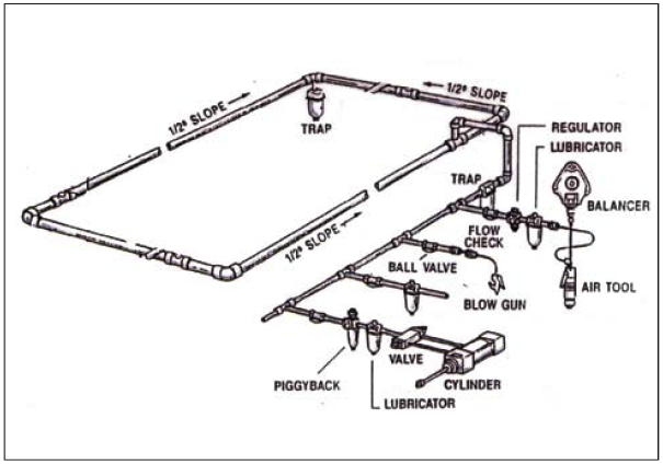
Rapidair Compressed Air Piping System
Diameter of pipe. Length of pipe. Number of bends, couplings, etc.
Compressed Air Piping Design Handbook
Air flow through pipe Air flow To start, you need to know the air flow through your system. The easiest way to find out the (maximum) air flow, is too look at the specs of your compressor (look in the manual or search online). There will always be one line that tells you the maximum output of the machine in liters/second, m3 per minute or hour, or cubic feet per minute (cfpm).
This is the maximum amount of air the compressor is able to pump out, at the rated pressure. But be careful, there is one important thing to look out for l/s vs. Nl/s (or cfpm vs Scfpm). The air flow that is stated in the compressor specs, is most of the time Nl/s (or S cfpm), which means “Normal liters per second” (or standard cubic feet per minute). It means that the values are given at standard or reference conditions, which are 1 bar, 20 degrees Celsius and 0% relative humidity. Often, the flow is stated as FAD, which means “Free Air Delivery”, which means the same thing: calculated back to reference conditions (more or less atmospheric air, like you and me breathe). So in fact, the FAD (Normal liters per second, or Scfpm), is actually the amount of air that is sucked in by the compressor per minute.
It is compressed, and then transported through the piping system. So at 7 bar pressure, the liters per minute (without the ‘normal’ ) is about 7 times smaller compared to the normal liters per second.
This difference is so often overlooked; most people don’t know about it and use the wrong terminology (even in compressor specifications sometimes!). Compressed air pipe size table Now instead of giving you complicated formulas to calculate the pressure drop, here is a simple table that will answer all your pipe sizing questions. Look up your compressors maximum flow rate in the left column. Now, measure or calculate the total length of your compressed air pipes and look it up in the top row. Now you can read the correct pipe size (in mm diameter) in the table.
This table is for 7 bars and maximum 0.3 bar pressure drop. The value given is for a straight pipe without any bends, couplings or other restrictions. How to calculate the influence of those can be found in the next paragraph.
Table 1: Compressed air pipe sizing table (in millimeters).